Paper Menu >>
Journal Menu >>
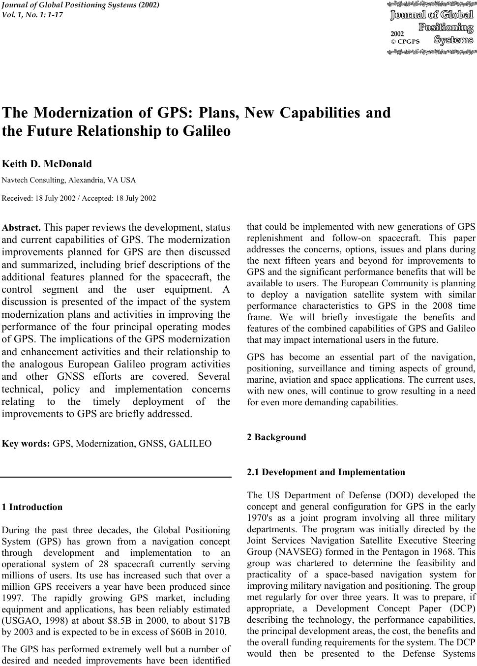 Journal of Global Positioning Systems (2002) Vol. 1, No. 1: 1-17 The Modernization of GPS: Plans, New Capabilities and the Future Relationship to Galileo Keith D. McDonald Navtech Consulting, Alexandria, VA USA Received: 18 July 2002 / Accepted: 18 July 2002 Abstract. This paper reviews the development, status and current capabilities of GPS. The modernization improvements planned for GPS are then discussed and summarized, including brief descriptions of the additional features planned for the spacecraft, the control segment and the user equipment. A discussion is presented of the impact of the system modernization plans and activities in improving the performance of the four principal operating modes of GPS. The implications of the GPS modernization and enhancement activities and their relationship to the analogous European Galileo program activities and other GNSS efforts are covered. Several technical, policy and implementation concerns relating to the timely deployment of the improvements to GPS are briefly addressed. Key words: GPS, Modernization, GNSS, GALILEO 1 Introduction During the past three decades, the Global Positioning System (GPS) has grown from a navigation concept through development and implementation to an operational system of 28 spacecraft currently serving millions of users. Its use has increased such that over a million GPS receivers a year have been produced since 1997. The rapidly growing GPS market, including equipment and applications, has been reliably estimated (USGAO, 1998) at about $8.5B in 2000, to about $17B by 2003 and is expected to be in excess of $60B in 2010. The GPS has performed extremely well but a number of desired and needed improvements have been identified that could be implemented with new generations of GPS replenishment and follow-on spacecraft. This paper addresses the concerns, options, issues and plans during the next fifteen years and beyond for improvements to GPS and the significant performance benefits that will be available to users. The European Community is planning to deploy a navigation satellite system with similar performance characteristics to GPS in the 2008 time frame. We will briefly investigate the benefits and features of the combined capabilities of GPS and Galileo that may impact international users in the future. GPS has become an essential part of the navigation, positioning, surveillance and timing aspects of ground, marine, aviation and space applications. The current uses, with new ones, will continue to grow resulting in a need for even more demanding capabilities. 2 Background 2.1 Development and Implementation The US Department of Defense (DOD) developed the concept and general configuration for GPS in the early 1970's as a joint program involving all three military departments. The program was initially directed by the Joint Services Navigation Satellite Executive Steering Group (NAVSEG) formed in the Pentagon in 1968. This group was chartered to determine the feasibility and practicality of a space-based navigation system for improving military navigation and positioning. The group met regularly for over three years. It was to prepare, if appropriate, a Development Concept Paper (DCP) describing the technology, the performance capabilities, the principal development areas, the cost, the benefits and the overall funding requirements for the system. The DCP would then be presented to the Defense Systems 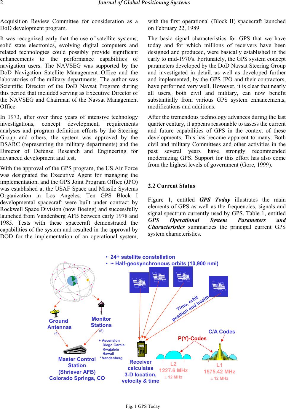 2 Journal of Global Positioning Systems Acquisition Review Committee for consideration as a DoD development program. It was recognized early that the use of satellite systems, solid state electronics, evolving digital computers and related technologies could possibly provide significant enhancements to the performance capabilities of navigation users. The NAVSEG was supported by the DoD Navigation Satellite Management Office and the laboratories of the military departments. The author was Scientific Director of the DoD Navsat Program during this period that included serving as Executive Director of the NAVSEG and Chairman of the Navsat Management Office. In 1973, after over three years of intensive technology investigations, concept development, requirements analyses and program definition efforts by the Steering Group and others, the system was approved by the DSARC (representing the military departments) and the Director of Defense Research and Engineering for advanced development and test. With the approval of the GPS program, the US Air Force was designated the Executive Agent for managing the implementation, and the GPS Joint Program Office (JPO) was established at the USAF Space and Missile Systems Organization in Los Angeles. Ten GPS Block I developmental spacecraft were built under contract by Rockwell Space Division (now Boeing) and successfully launched from Vandenberg AFB between early 1978 and 1985. Tests with these spacecraft demonstrated the capabilities of the system and resulted in the approval by DOD for the implementation of an operational system, with the first operational (Block II) spacecraft launched on February 22, 1989. The basic signal characteristics for GPS that we have today and for which millions of receivers have been designed and produced, were basically established in the early to mid-1970's. Fortunately, the GPS system concept parameters developed by the DoD Navsat Steering Group and investigated in detail, as well as developed further and implemented, by the GPS JPO and their contractors, have performed very well. However, it is clear that nearly all users, both civil and military, can now benefit substantially from various GPS system enhancements, modifications and additions. After the tremendous technology advances during the last quarter century, it appears reasonable to assess the current and future capabilities of GPS in the context of these developments. This has become apparent to many. Both civil and military Committees and other activities in the past several years have strongly recommended modernizing GPS. Support for this effort has also come from the highest levels of government (Gore, 1999). 2.2 Current Status Figure 1, entitled GPS Today illustrates the main elements of GPS as well as the frequencies, signals and signal spectrum currently used by GPS. Table 1, entitled GPS Operational System Parameters and Characteristics summarizes the principal current GPS system characteristics. 1 ON3 men u 2 Rockwell 456 7 WPT 8 POS 9 NAV CLR MARK 0 OFF NUM LOCK FIX FOM 1 N 42* 01” 46.12” W 091* 38’ 54.36” EL + 00862 ft ZERO IZE Ground Antennas (4) Monitor Stations (5) Master Control Station (Shriever AFB) Colorado Springs, CO Receiver calculates 3-D location, velocity & time C/A Codes Time, orbit position and health •24+ satellite constellation •~ Half-geosynchronous orbits (10,900 nmi) L2 1227.6 MHz ±12 MHz +Ascension Diego Garcia Kwajalein Hawaii * Vandenberg L1 1575.42 MHz ±12 MHz P(Y)-Codes Fig. 1 GPS Today  McDonald: The Modernization of GPS 3 The general characteristics of the ground segment are given in Figure 2 entitled GPS Ground Control System and similar information for the GPS spacecraft (S/C) deployment is given in Figure 3 entitled GPS Space Segment. Monitor Stations Ground Antennas Master Control Station (Schriever AFB) HAWAII CAPE CANAVERAL COLORADO SPRINGS ASCENSION DIEGO GARCIA KWAJALEIN VANDENBERG GPS Constellaton Master Control Station (MCS):Satellite control, system operations Alternate Master Control Station:Training, back-up zMonitor Station (MS):L-band; Collect range data, monitor nav signals ▲Ground Antenna (GA):S-band; Transmit data/commands, collect telemetry Fig. 2 GPS Operational Control System (OCS) Tab. 1 GPS Operational System Parameters and Characteristics 2.22.99kdm Space SegmentControl SegmentUser Segment 24 GPS spacecraft (S/C) in orbit is the baseline constellation 6 orbit planes spaced 60°apart (LAN) 4 S/C per orbit plane; >4 for > 24 constel 10,898 n.mi. (20,180 km) orbit altitude 55° S/C orbit plane inclination Near circular orbits (e ≈ 0) 11 hr 58 min S/C orbital period Provides PRN-coded ranging signals Circularly polarized transmissions Frequencies and PRN codes: 1575.42 ± 12 MHz: L1 band 1227.6 ± 12 MHz: L2 band 1176.45 ± 12 MHz: L5 band 1.023 Mbps = C/A-code bit rate 10.23 Mbps = P/Y-code bit rate 1msec = period of C/A-codes 7 days = period of P/Y-codes (each S/C) 1 GPS S/C per launch (Delta II) C/A-codes in the clear (SA removed) P/Y and M-codes, secure (encrypted) Data message: 50 bps (mod 2 encoded) S/C lifetimes: II, IIA -7.5 years; IIR -7.5 +years; IIF: 12-15 years S/C: Multiple Rb and Cs atomic clocks Civil GPS standalone accuracy: 5 - 10 m. - Military GPS accuracy: 2 – 9 m.- 14 -180 day S/C nav. message storage Headquarters & Master Control Station (MCS) at Schriever AFB, Col Spr, CO Uplink and monitor station locations: Schriever AFB Hawaii (monitor only) Ascension Island Kwajalein Diego Garcia Kennedy Ctr., FL (up-link backup)-- New monitor sites: 8 NIMA tracking stations MCS receives monitor station measure-- ments, 2f iono corrections, UTC time Large Kalman estimator at MCS MCS computes and schedules uplink transmissions that include: S/C ephemeris (orbital elements) S/C atomic clock corrections S/C almanac data Ionospheric delay model terms S/C health and status information Monitor stations linked to MCS Up-link antennas: 10 m. dishes Near continuous ant. visibility of GPS S/C Unified S-band tracking, telemetry & - command (TT&C) links Orbit and ephemeris accuracy (OCS): Passive receivers; no user transmissions required for navigation reception Receivers normally process signals from multiple (5-12) S/C simultaneously Number of S/C in view of unobstructed GPS receiver: 6-12 S/C (average 8) Coarse acquisition (C/A)-codes, 1.023 Mbps used normally by civil community and by military for acquisition of P/Y-code New M-code to provide direct access Spread spectrum signal; pseudorandom- noise coded: 1.023 Mbps & 10.23 Mbps 37 PRN C/A Gold codes available Direct sequence P/Y-code: 37+ weeks long; 1 week segment used for each S/C GPS receiver antennas normally are for L-band upper hemisphere coverage Signal power from S/C at receiver: -160 dBwfor L1 C/A-code signal -163dBwfor L1 P/Y- code signal -166dBwfor L2 P/Y- code signal Modernized L1, L2 and L5 signals are planned for current L1 C/A pwror more Differential GPS accuracy: 1 mm - 3 m. Digital correlation receivers are small, light and reliable. 8M+ in service (1/02) 24 GPS spacecraft (S/C) in orbit is the baseline constellation 6 orbit planes spaced 60°apart (LAN) 4 S/C per orbit plane; >4 for > 24 constel 10,898 n.mi. (20,180 km) orbit altitude 55° S/C orbit plane inclination Near circular orbits (e ≈ 0) 11 hr 58 min S/C orbital period Provides PRN-coded ranging signals Circularly polarized transmissions Frequencies and PRN codes: 1575.42 ± 12 MHz: L1 band 1227.6 ± 12 MHz: L2 band 1176.45 ± 12 MHz: L5 band 1.023 Mbps = C/A-code bit rate 10.23 Mbps = P/Y-code bit rate 1msec = period of C/A-codes 7 days = period of P/Y-codes (each S/C) 1 GPS S/C per launch (Delta II) C/A-codes in the clear (SA removed) P/Y and M-codes, secure (encrypted) Data message: 50 bps (mod 2 encoded) S/C lifetimes: II, IIA -7.5 years; IIR -7.5 +years; IIF: 12-15 years S/C: Multiple Rb and Cs atomic clocks Civil GPS standalone accuracy: 5 - 10 m. - Military GPS accuracy: 2 – 9 m.- 14 -180 day S/C nav. message storage Headquarters & Master Control Station (MCS) at Schriever AFB, Col Spr, CO Uplink and monitor station locations: Schriever AFB Hawaii (monitor only) Ascension Island Kwajalein Diego Garcia Kennedy Ctr., FL (up-link backup)-- New monitor sites: 8 NIMA tracking stations MCS receives monitor station measure-- ments, 2f iono corrections, UTC time Large Kalman estimator at MCS MCS computes and schedules uplink transmissions that include: S/C ephemeris (orbital elements) S/C atomic clock corrections S/C almanac data Ionospheric delay model terms S/C health and status information Monitor stations linked to MCS Up-link antennas: 10 m. dishes Near continuous ant. visibility of GPS S/C Unified S-band tracking, telemetry & - command (TT&C) links Orbit and ephemeris accuracy (OCS): Passive receivers; no user transmissions required for navigation reception Receivers normally process signals from multiple (5-12) S/C simultaneously Number of S/C in view of unobstructed GPS receiver: 6-12 S/C (average 8) Coarse acquisition (C/A)-codes, 1.023 Mbps used normally by civil community and by military for acquisition of P/Y-code New M-code to provide direct access Spread spectrum signal; pseudorandom- noise coded: 1.023 Mbps & 10.23 Mbps 37 PRN C/A Gold codes available Direct sequence P/Y-code: 37+ weeks long; 1 week segment used for each S/C GPS receiver antennas normally are for L-band upper hemisphere coverage Signal power from S/C at receiver: -160dBwfor L1 C/A-code signal -163dBwfor L1 P/Y- code signal -166dBwfor L2 P/Y- code signal Modernized L1, L2 and L5 signals are planned for current L1 C/A pwror more Differential GPS accuracy: 1 mm - 3 m. Digital correlation receivers are small, light and reliable. 8M+ in service (1/02) Space SegmentControl SegmentUser Segment  4 Journal of Global Positioning Systems •24-satellite (nominal) constellation •Six orbital planes, four satellites per plane •Semi-synchronous, circular orbits (~10,900 n. mi., 20,200 km.) Block II/IIA Block IIR Block IIF Fig. 3 GPS Space Segment The Block II operational spacecraft launches which began in early 1989 later incorporated slightly modified (Block IIA) spacecraft. These included some improvements including additional on-board data memory, providing an extended period (several months in lieu of 14 days) over which data could be transmitted from the S/C to users without ground uploads. The DOD contracted with Rockwell Space Division for 28 Block II and IIA spacecraft at a cost of about $1.2B. In July 1995, the full operational capability of GPS was achieved, consisting of a ground segment, a constellation of 24 operational GPS spacecraft providing navigation services worldwide and a variety of user equipment. Since that time, the GPS space segment has performed continuously with between 24 and 28 operational spacecraft. User equipment development and manufacture has increased dramatically, especially in the civil community. 2.3 The GPS Constellation The Block II and IIA spacecraft's limited lifetime in orbit, nominally about 7.5 years, establishes the need and schedule for replenishment spacecraft. The DOD contracted with Lockheed-Martin Astro-Space for twenty-one GPS third generation replenishment (Block IIR) spacecraft. In January 1997, the first of the Block IIR spacecraft was launched but did not achieve orbit when a strap-on booster failed on its newly configured Delta II launch vehicle. A later launch in July of 1998 and all subsequent launches have been successful. As of 1998, all 28 of the initial Block II (and IIA) operational spacecraft have been launched. The remaining Block IIR spacecraft, including nine to twelve S/C planned for modernization, will phase in to provide the principal operational signals and capabilities for the system during the next ten years or more. The DOD has contracted with the Boeing Space Division for a fourth generation follow-on GPS (Block IIF) spacecraft. Although a buy of 30-33 spacecraft was originally planned, modernization requirements have resulted in the need for a new generation of spacecraft beyond the IIF. To this end, the GPS Block III’s are in development. The Block III’s will replace all but twelve of the originally planned Block IIF spacecraft. The first six IIF spacecraft are on contract and an additional six are planned for GPS mid-term constellation sustainment purposes. Beyond that, the new Block III spacecraft will be deployed. The Block IIR, IIF and III spacecraft provide the principal space vehicles available for the enhancement and modernization of GPS. It is the periodic replenishment of the spacecraft constellation that provides the opportunity for implementing upgrades and modernization features to the system. Since the lead time for acquiring a new generation of GPS spacecraft is long (typically 5-8 years), and the full deployment of a new constellation requires a number of years (typically 7-10 years), the introduction  McDonald: The Modernization of GPS 5 of improvements to GPS is normally a slow and gradual process. 2.4 The Navigation Signals GPS spacecraft currently transmit navigation signals to the earth at two frequencies, designated L1 and L2 (refer to Figure 1). L1 is the principal GPS carrier signal, at a frequency of 1575.42 MHz. This signal is modulated by two types of pseudo-random noise (PRN) codes, termed the coarse/acquisition (C/A) codes, at a bit rate (or "chipping" rate) of 1.023 Mcps, and the precision/secure (P/Y) codes, at a chipping rate of 10.23 Mcps. The GPS L2 signal, transmitted by the spacecraft at 1227.6 MHz, was established to provide a second frequency for ionospheric group delay corrections to GPS user receivers. Since the ionosphere is a dispersive medium with close to a 1/f2 dependence, the combination of the L1 and L2 frequencies provides an excellent real time technique for determining the group delay effects on the GPS signal paths caused by the refraction of the signal paths by the free electron content in the ionosphere. Ionospheric errors, if uncorrected, can contribute the largest single propagation error to GPS operation, causing ranging errors of up to 40 meters. The GPS L2 signal was originally implemented primarily for correction of the slowly changing ionospheric delay. For this reason, it is transmitted at a lower power level (at about one fourth, or -6dB) relative to the L1 C/A-code signal. The P/Y-code signals on L1 and L2 are normally secure, so the full capabilities of these signals are accessible only to DOD or other authorized users. (No data message on L5 quadrature signal) Current Modernized Current Modernized Frequency in MHz Frequency in MHz Aeronautical Radionavigation Services (ARNS) Band Radionavigation Satellite Services (RNSS)Band 1215 1227.6 1575.42 1575.42 L2 L1 L1 L2 P/Y-codesP/Y-codes C/A-codes (for civil & military use) C/A-codes C/A-codes C/A-codes C-codes (new) L2 1176.45 1164.45 1188.45 1575.42 1227.6 P/Y-codes P/Y-codes Civil Signals 1563.42 1587.42 1575.42 (L1) 1215.6 1239.6 1227.6 (L2) L5 RNSS Bands 1215-1240 1560-1610 MHz 960-1215 MHz Note 1:Military M-codes are in definition. L5 codes (I& Q-codes) are specified Note 2: Modulation envelopes for only the code principal signal lobes are shown. Note 3:Phase quadrature signals are shown below the origin lines. I5, Q5-codes (new) Freque ncy Freque ncy Military Signals M-codes M-codes Fig. 4 GPS Signal Evolution and Spectrum Occupancy signals transmitted by GPS and the planned evolution to additional codes and signal frequencies. 2.5 GPS Performance GPS has a number of different modes of operation, each with its own set of performance capabilities. First, GPS can be used autonomously (on a stand-alone basis), i.e. without any augmentations. In this case, the user equipment receives and uses only the signals received from the constellation of spacecraft to determine user position, velocity, time (PVT) and related parameters. GPS can also be used in a differential mode in which known navigation data or ranging data received at a reference location and time are compared (or differenced) with similar GPS measured data at the same point and time. The corrections from this process are then applied at the same time (or with minimum latency) to the GPS measured data taken at a remote point. For real-time operation, a data link between the reference receiver and the remote receiver is normally used to communicate the corrections. This process has the great advantage of canceling the fixed, or slowly varying, (bias) errors in measurement that have the same effect at both locations. The differential correction technique, 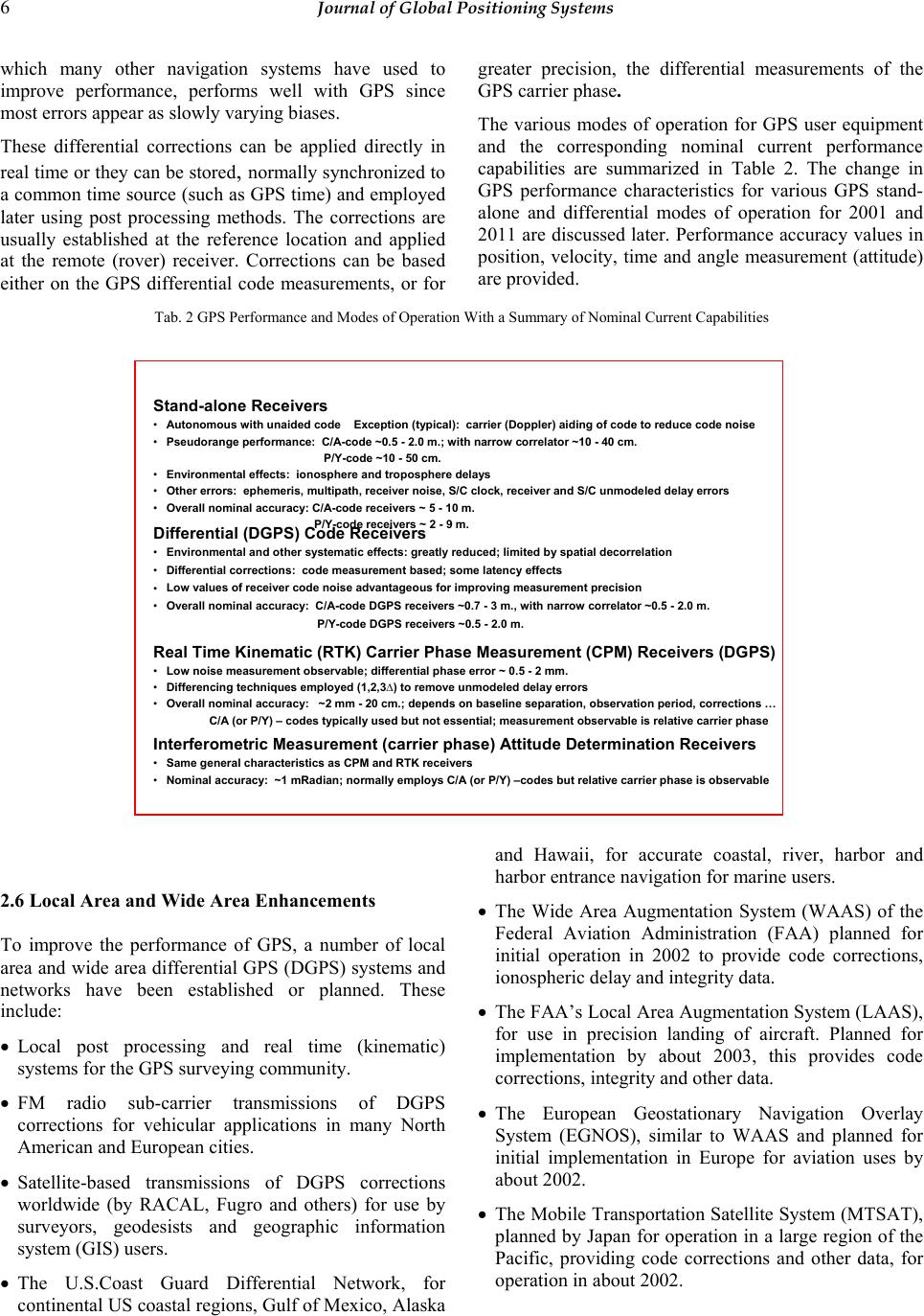 6 Journal of Global Positioning Systems which many other navigation systems have used to improve performance, performs well with GPS since most errors appear as slowly varying biases. These differential corrections can be applied directly in real time or they can be stored, normally synchronized to a common time source (such as GPS time) and employed later using post processing methods. The corrections are usually established at the reference location and applied at the remote (rover) receiver. Corrections can be based either on the GPS differential code measurements, or for greater precision, the differential measurements of the GPS carrier phase. The various modes of operation for GPS user equipment and the corresponding nominal current performance capabilities are summarized in Table 2. The change in GPS performance characteristics for various GPS stand- alone and differential modes of operation for 2001 and 2011 are discussed later. Performance accuracy values in position, velocity, time and angle measurement (attitude) are provided. Tab. 2 GPS Performance and Modes of Operation With a Summary of Nominal Current Capabilities Differential (DGPS) Code Receivers •Environmental and other systematic effects: greatly reduced; limited by spatial decorrelation •Differential corrections: code measurement based; some latency effects •Low values of receiver code noise advantageous for improving measurement precision •Overall nominal accuracy: C/A-code DGPS receivers ~0.7 - 3 m., with narrow correlator ~0.5 - 2.0 m. P/Y-code DGPS receivers ~0.5 - 2.0 m. Stand-alone Receivers •Autonomous with unaided code Exception (typical): carrier (Doppler) aiding of code to reduce code noise •Pseudorange performance: C/A-code ~0.5 - 2.0 m.; with narrow correlator ~10 - 40 cm. P/Y-code ~10 - 50 cm. •Environmental effects: ionosphere and troposphere delays •Other errors: ephemeris, multipath, receiver noise, S/C clock, receiver and S/C unmodeled delay errors •Overall nominal accuracy: C/A-code receivers ~ 5 -10 m. P/Y-code receivers ~ 2 -9 m. Real Time Kinematic (RTK) Carrier Phase Measurement (CPM) Receivers (DGPS) •Low noise measurement observable; differential phase error ~ 0.5 - 2 mm. •Differencing techniques employed (1,2,3∆) to remove unmodeled delay errors •Overall nominal accuracy: ~2 mm -20 cm.; depends on baseline separation, observation period, corrections … C/A (or P/Y) – codes typically used but not essential; measurement observable is relative carrier phase Interferometric Measurement (carrier phase) Attitude Determination Receivers •Same general characteristics as CPM and RTK receivers •Nominal accuracy: ~1 mRadian; normally employs C/A (or P/Y) –codes but relative carrier phase is observable 2.6 Local Area and Wide Area Enhancements To improve the performance of GPS, a number of local area and wide area differential GPS (DGPS) systems and networks have been established or planned. These include: • Local post processing and real time (kinematic) systems for the GPS surveying community. • FM radio sub-carrier transmissions of DGPS corrections for vehicular applications in many North American and European cities. • Satellite-based transmissions of DGPS corrections worldwide (by RACAL, Fugro and others) for use by surveyors, geodesists and geographic information system (GIS) users. • The U.S.Coast Guard Differential Network, for continental US coastal regions, Gulf of Mexico, Alaska and Hawaii, for accurate coastal, river, harbor and harbor entrance navigation for marine users. • The Wide Area Augmentation System (WAAS) of the Federal Aviation Administration (FAA) planned for initial operation in 2002 to provide code corrections, ionospheric delay and integrity data. • The FAA’s Local Area Augmentation System (LAAS), for use in precision landing of aircraft. Planned for implementation by about 2003, this provides code corrections, integrity and other data. • The European Geostationary Navigation Overlay System (EGNOS), similar to WAAS and planned for initial implementation in Europe for aviation uses by about 2002. • The Mobile Transportation Satellite System (MTSAT), planned by Japan for operation in a large region of the Pacific, providing code corrections and other data, for operation in about 2002.  McDonald: The Modernization of GPS 7 3 The Modernization of GPS Although GPS has performed extremely well and has generally exceeded expectations, some significant improvements are needed. A number of committees, representing both government and civil communities, have investigated the system's needs and deficiencies over the past decade in order to determine what capabilities and features should be incorporated into a future GPS to satisfy both military and civil users. The modernization of GPS is a difficult and complex enterprise. It involves not only addressing civil and military needs and costs for performance improvements, but also issues with far-reaching implications in other areas. These issues include spectrum needs and use, security, civil and military performance, system integrity, signal availability, institutional concerns on GPS financing and management, and the future operation of GPS as a national and international resource. Fortunately, many of the critical issues have been identified and are resolved or appear to be near final resolution. If all goes as planned, or as hoped, it becomes reasonably clear what can be expected in the next decade. However, this assumes an optimistic view of the commitment of the U.S. government to provide the decisions, the institutional arrangements and the funding necessary to meet the generally agreed upon needs in a timely manner. 3.1 Signals and Signal Separation Initially, the military GPS planners wanted to separate their GPS frequencies from those used for civil applications. This separation was intended to avoid signal interference and interactions and to provide maximum flexibility for both user groups. An intensive search, however, failed to find any new spectrum that would satisfy the military requirements. Therefore, the military decided that their signals will remain within the current 24 MHz bands authorized by the ITU for GPS in the Radionavigation Satellite Services (RNSS) band at L1 (1563.42-1587.42 MHz) and L2 (1215.6-1239.6 MHz). Additional Signal Needs It has been agreed for several years that additional GPS signals are needed for civil applications. These signals are required for a) reducing the ionospheric errors by use of the two frequency correction technique, b) for increased signal robustness, especially in aviation safety operations, and c) for improved acquisition and accuracy. Concerns on L2 and a New L5 The FAA for some time has opposed the use of L2 for aviation safety applications. Their concern is that since the International Telecommunications Union (ITU) has authorized this band for use on a co-primary basis with radiolocation services (including high power radars), that aircraft using the band may be subject to unacceptable levels of interference. Since this may compromise aviation safety operations, the FAA considers the L2 band unacceptable. The FAA requested a GPS aviation frequency in the Aeronautical Radionavigation Services (ARNS) band, which is located directly below the GPS L2 band. As we will discuss, this has occurred. The Presidential Decision Directive (PDD) on GPS of March 29, 1996 (Gore and Pena, 1996) stated that both the L1 and L2 frequency bands would be available for civil use and that a third civil signal would also be authorized. Although the L1 and L2 frequency bands can satisfy most civil users, aviation users need a third civil frequency to replace the L2 band and its limitations in safety-of-life applications. After an intensive search for new frequencies by the Department of Transportation (DOT), the Department of Defense (DOD) and other agencies, Vice President Gore announced on January 25, 1999 that a region in the ARNS band had been agreed upon as the new (third) civil frequency. This frequency is referred to as L5 and is centered at 1176.45 MHz. This selection appears to satisfy aviation safety uses. Figure 5 illustrates the arrangement in the spectrum now planned for the modernized signals, showing the ARNS band below the GPS L2 band. Prior to operational use of L5, coordination with other systems in the band as well as approval by the International Telecommunications Union (ITU) is required. The ARNS band is currently established by the ITU for ground-to-air services. For part of this band to be used by GPS requires an ITU satellite-to-earth transmission classification. This matter was favorably considered at the ITU World Radio Conference held in April, 2000 in Istanbul. It was expected that the international aviation community would support this change. 3.2 New and Retained GPS Signals For backward compatibility (or “legacy”) purposes, the existing C/A-codes on L1 and the P/Y-codes on L1 and L2 are to be retained. Continuation of these codes is necessary until modernized GPS spacecraft transmitting the new GPS signals for both civil and military users are deployed. New GPS user equipment also needs to be produced to operate with the modernized signals.  8 Journal of Global Positioning Systems Band Assignments: 1559 1610 1563.42 GPS L1 1605 1595 1587.42 MSS GLONASS L1 1215 GPS L5 1188.45 1164.45 1240 GPS L2 1260 GLONASS L2 1239.6 JTIDS… ARNS BandRNSS Band RNSS Band L5 L2 L1 1250 RNSS - Radionavigation Satellite Services Band ARNS - Aeronautical Radionavigation Services Band JTIDS - Joint Tactical Information Distribution System (DoD) GLONASS - Glonass Navigation Satellite System (Russian Federation) MSS – Mobile Satellite Services Band 1575.42 1176.45 1227.6 Fig. 5 GPS and GLONASS Signal Placement Arrangement: L1, L2 and L5 Signal Codes The current plans are to continue providing the civil community with the C/A-codes on L1, and to transmit newly configured C-codes (or sometimes referred to as CS-codes) on L2 from subsequent spacecraft when feasible. Plans for the L5-codes are for a higher bit (chip) rate and longer codes than the current C/A-codes or the new C-codes. The proposed codes on L5 consist of a 10.23 Mcps code rate with a code length of 10,230 bits (in one millisecond). This is the same code period as the C/A-codes. Compared to the C/A-codes, the longer, high rate code sequences provides improved ranging accuracy, a lower code noise floor, acceptable acquisition times, •Safety-of-life applications(e.g., civil aviation) •In Aeronautical Radio Navigation Service (ARNS) band •Two signals:(a) In-phase signal (I5) with data message (b) Quadrature signal (Q5); no data message for improved tracking •Higher accuracy when used with civil codes on L1 or L2 –Similar accuracy as military signals today (P/Y-codes) –More robust than current C/A-codes on L1 –Greater resistance to interference than C/A-codes –Higher chipping rate improves multipath performance –Plans are to have about four times greater power (needed to operate in ARNS band that has higher noise and interference levels) –Improved data message (and shortened) 1176.45 MHz 1186.68 MHz 1166.22 MHz Fig. 6 L5 - New Civil Signal  McDonald: The Modernization of GPS 9 better isolation (cross-correlation properties) between codes, and substantially reduced multipath interference susceptibility. Figure 6 entitled L5 – New Civil Signal shows the main spectral characteristics of the L5 in-phase and quadrature codes referred to as the I5 and Q5-codes. To take full advantage of L5, it is planned for one of the two quadrature signals to be transmitted without data modulation. The “data free” signal provides advantages for accurate phase tracking and more precise carrier phase measurements, of special interest to the survey and scientific communities. Similarly, the new C-codes on L2 are at the C/A-code chipping rate (1.023 Mcps) and are time multiplexed to provide a data free signal as well as a signal with data. The current P/Y-coded signals on L1 and L2 perform very well. However, because of the extremely long sequence length (~1013 bits), and the corresponding period of this code (7 days), acquisition of the P/Y-code is very difficult unless some precise knowledge of the system timing is known. The P/Y-code acquisition normally involves first, the acquisition of the short sequence (1 ms) C/A-codes on L1. The C/A-code message contains system timing data (in the hand-over, or HOW, word) that provides an authorized user with information for acquiring the P/Y-code. However, the military believes it essential in the future to acquire their secure signals without first accessing the C/A-codes. The C/A-codes are available to civil users and others. The military requirement for direct acquisition of their secure signal appears to require the transmission of a set of new military codes, called the M-codes. Code Options Considered Initially, the DoD indicated that it planned to place its new signals in the center of the L1 and L2 bands, similar to their C/A and P/Y-codes. To minimize interactions with the main part of the DoD signals, it appeared advantageous for the civil signals to avoid the center of the bands. The author proposed on several occasions during 1997-98 the use of pairs of coded signals (offset from each band center) in the L1 and L2 bands (McDonald, 1998a,b). The use of civil “separated carriers” or “split spectrum” signals in the outer regions of the bands where the military signals would be at a low level provided separation between the military and civil signals. It also provided some significant advantages for precise carrier phase measurements and more precise code processing. These split spectrum signals were then found to have excellent performance properties, especially compared to the current military P/Y-code signals, and to be easily implemented (Spilker et al., 1998). During the past two years the DoD has sponsored a number of investigations of split spectrum signals and has selected this signal as their new M-code signal for their use at both L1 and L2. The final arrangement for the M-code signals appear to use a secure M-code with a bit rate of about five Mbps modulated on dual "split spectrum" carriers that are spaced about 10 MHz above and below the centers of the GPS L1 and L2 bands [at the first nulls in the current P(Y)-code structure]. The GPS JPO and their contractors have investigated the military signal alternatives and are responsible for the final selection. 4 Security Issues Selective Availability A number of Committees have investigated the need and effectiveness of SA. Almost all of these, both civil and military, have found that SA is not effective, is easily mitigated (for example, by the use of differential techniques) and that it is costly to continue, especially to civil users. Several of the groups strongly recommended that SA be removed immediately (NRC, 1995; NAPA, 1995). The Presidential Decision Directive on GPS released on March 29, 1996 stated that the continuance of SA would be reviewed annually by the President starting in 2000 and that SA would be discontinued no later than 2006. The civil community has consistently recommended that SA be removed. However, users adapted quickly to the use of SA mitigation techniques, principally by the use of differential corrections. GPS Accuracy Improvements and Performance Augmentations On May 1, 2000, the White House announced that the Selective Availability degradation would be removed starting at midnight, May 1, and that there were no plans or intentions to restore it in the future. The substantial improvement in stand-alone GPS accuracy to civil users has become apparent. Even at the time of the solar maximum effects on the ionosphere (in 2000-2001), performance of SPS receivers is now typically at the 5-10 meter level. The removal of SA combined with the availability of a second (and third) civil signal frequency can improve GPS stand-alone civil horizontal accuracy to the 1-3 meter range (at a 95% confidence level). The removal of SA also has a substantial impact on reducing DGPS data link capacity requirements because of the reduced need for frequent SA corrections. Military Signal Security Current military users normally access the C/A-coded signals but their security system corrects for the effects of the SA degradation. The DoD encryption of the P-code to form the Y-code not only limits access to the most accurate codes to military (and other authorized) users but also provides anti-spoof (A-S) protection. The current plan is for the P/Y-coded signals to be retained until the  10 Journal of Global Positioning Systems new M-code signals are generally available. The phase- over interval can be expected to last until 2015 and possibly longer. The new M-code signals will also be secure. They differ from the P/Y-code signals in that they provide improved performance and are planned to be directly accessed. The military M-code signal structure is in final development. Figure 7 entitled New Military Signals : M-Code shows the general characteristics of the military P(Y) and the planned M-code signals. 1563 1575 1587 1215 1227 1239 •Anti-jam through higher power •Robust and autonomous acquisition •Spectral isolation from civil signals •Improved security (exclusivity, authenticity, confidentiality) •Better performance •Flexibility •Compatibility with C/A-code and P(Y)- code receivers •Operation within existing L1 and L2 bands Frequency in MHz Fig. 7 New Military Signals: M-code 5 GPS Accuracy Improvements and Performance Augmentations Ionospheric Errors Ionospheric propagation group delay effects on GPS signals cause most of the residual receiver error. These delay effects vary considerably depending on random effects, the time of day, season of the year and the activity state of the 11-year period solar (sunspot) cycle. Figure 8 entitled Solar Cycle 23 Sunspot Number Prediction provides a graphic indication of the cyclic character of the solar emissions that affect the earth’s ionosphere. The ionospheric propagation delay error effects can be effectively removed by using the two frequency ionospheric correction technique that the military now uses. For this reason, there has been interest for many years in a second frequency for civil GPS users. As indicated earlier, agreement has been reached within the government to incorporate a second civil signal (at L2) and a third civil signal (L5, in the ARNS band at 1176.45 MHz) in future Block IIF spacecraft. The excellent capabilities of these signals for ionospheric correction can improve the civil accuracy for stand-alone GPS users to the 1-3 meter level, or better. Unfortunately, the current schedule for the deployment of enough Block IIF spacecraft (about 18 are required) to allow confident access to the L5 signals is over a decade away. A reasonable estimate for the date at which full operational reception of L5 signals would be about 2015, depending on the lifetime of the IIA, IIR and IIF spacecraft. Receiver Noise Errors Other factors that influence GPS user equipment accuracy include the number of parallel receive channels available to a receiver, the receiver’s code noise performance, its susceptibility to multipath, and the errors associated with implementing, or mechanizing, the solutions. The number of GPS receiver channels corresponds to the maximum number of spacecraft that can be simultaneously tracked. Ideally, the number of channels is large enough to provide continuous all-in-view tracking of the visible GPS spacecraft, since this provides the best geometric performance. Although the receiver code noise for a conventional C/A- code receiver (with carrier aiding) is equivalent to a ranging error of about one meter, code noise errors for  McDonald: The Modernization of GPS 11 Fig. 8 Cycle 23 Sunspot Number Prediction (September 200) "narrow correlator" C/A-code receivers can be as low as 10-20 cm. Implementation errors are usually small or negligible. Receiver thermal noise performance at the 10 cm. to 1 m. level is considered good, however GPS precise carrier phase measurements are typically considerably better, nominally at the 0.5-2 mm. equivalent noise level. Control Segment Errors The GPS control segment determines the quality of the GPS spacecraft orbital elements and timing data. These are uploaded to the GPS spacecraft memory and then periodically transmitted to the users in the GPS data message. This spacecraft position and other data directly affect user accuracy. Moreover, since it degrades with time, the data is influenced by the update rate of the uploads to the GPS spacecraft. Recent improvements in the control segment provide spacecraft ephemeris accuracy at the 1-2 meter level. The planned addition of six ground stations of the National Imagery and Mapping Administration (NIMA) to the GPS tracking network will substantially improve the quality and timeliness of the GPS tracking measurements and the computed parameters. More frequent uploads to the spacecraft are also planned. In the 2000-2010 period, sub-meter ephemeris accuracy, which will improve to the decimeter range, is expected for the GPS tracking network and the Operational Control System. Autonav Operation The GPS constellation may be required to operate without the GPS ground segment for an extended period. By accurately ranging to other spacecraft using the GPS inter-satellite link the Block IIR, IIF and III spacecraft can operate in an autonomous navigation (autonav) mode. The autonav ranging data is cross-linked to other spacecraft in the constellation to provide continuous on- board information that is used to autonomously compute accurate new ephemeris data for each spacecraft. This data, incorporating the measured GPS spacecraft orbital perturbations, can provide excellent system accuracy over an extended period (several months). Position Accuracy Estimates for 2002 and 2012 Figure 9, entitled Position Accuracy Estimates for Civil and Military GPS Receivers for 2000 to 2010 illustrates the anticipated system performance improvements in GPS as reflected in GPS receivers operating in their various modes. This chart addresses position accuracy only, however there are many other measurements that will be affected as well. A brief summary of the additional measurement parameters and their estimated accuracy is given in Table 3, entitled GPS Performance in Various Modes of Operation for 2000 and 2010.  12 Journal of Global Positioning Systems 2000 2010200506 07 08 09 1 m 10 cm 1 cm 1 mm 10 m 100 m 1 m 10 cm 1 cm 1 mm 10 m 100 m 1 m 10 cm 1 cm 1 mm 10 m 100 m Current Civil GPS Systems Standard Positioning Svc. (SPS) C/A-code (1.023 Mcps)on L1 (1575.42 MHz) L2 (1227.6 MHz) carrier phase ionospheric delay correction *Note:Selective Availability degradation of SPS at ~60 m. level until 1 May 2000 60 m 6 m 2 m 50 cmDGPS receiver using C/A-code (C2) Carrier aided; separation of ~20-200km Stand-alone C/A-code receiver (Current 1) 30 cm 7 cm RTK, Real Time Kinematic(C3) ; carrier phase measurement receiver;L1 only 2 cm 5 mmSurvey receiver w. post processing (C4) carrier fmeas’dat L1 & L2 for iono-correction Future SPS Systems (Using New Civil GPS Signals) C/A-codes (1.023 Mcps) on L1 (1575.42 MHz) and L2 (1227.6 MHz L5-codes (I5,Q5 at 10.23 Mcps) on L5 (1176.45 MHz) Note: L5-codes: I5 on L5 with data msg. Q5 (quad. signal) on L5, no data msg. Current 1 C2 C3 C4 Degrades with solar cycle max at ~2011 Stand-alone SPS receiver (Future 1) C/A- codes on L1, L2 F2 2.0 m Precision SPS stand-alone receiver (F2) C/A-codes on L1, L2 and I,Q -codes on L5 3.0 m 3 cmReal Time Kinematic receiver (F3); carrier φ C/A-codes on L1, L2; I5, Q5-codes on L5 5 mmSurvey receiver/post process’g (F4); carr. φ C/A-codes on L1, L2 ; I5, Q5-codes on L5 F3 F4 6 m5 mMilitary PLGR stand-alone receiver (Mil. 1) C/A and P/Y- codes at L1 only 2 m 0.8 mMilitary (2f) stand-alone receiver (M2) PPS: C/A +P/Y or M-codes; on L1 & L2 50 cmMilitary DGPS receiver (M3) PPS: C/A +P/Y or M-codes; on L1 & L2 M 3 Year Note: IOC for M-codes and C/A-codes on L2 ~08+; current plans call for L5 signals IOC at 2012+ Future 1 2 m Position Accuracy in meters Position Accuracy in meters Position Accuracy in meters Position Accuracy = Horizontal position accuracy at 95% confidence level. Note: SPS = Standard Positioning Service PPS = Precise Positioning Service Current and Future Military Systems (PPS) (Using existing or new signals) C/A-codes on L1 (& L2) and P/Y-codes on L1 and L2 and/or (evolving to) M-codes on L1 and L2 Note: M-codes are the new Military codes planned as L1, L2 split spectrum signals M 2 Military 1 Note: Current plans call for M-codes IOC at ~2008 2 - 4 m. 7 m3-5 m. F1 Fig. 9 Position Accuracy Estimates for Civil and Military GPS Receivers in Various Modes of Operation for the 2000 to ~2010+ Time Period Tab. 3 GPS Performance in Various Modes of Operation - for 2000 and 2010 Accuracy estimates for 95% confidence in horizontal; vertical accuracy is about 1.4 x horizontal dimension Position Velocity Time Comments Mode of Operation Conventional civil stand-alone SPS: C/A-code E.g., PLGR (P/Y) Iono dependent C/A-code differential Standard Positioning Service (SPS) L1 L2 L5 GPS Bands Code differential *SPS: C/A-codes at L1 and L2 Precision stand-alone w 3f’s *SPS: C/A &L5 I,Q-codes 2000 2010 2000 2010 2000 2010 SA Real time kinematic (RTK) SPS: C/A-code, carrier phase me as. Survey: Post-processing; long b SPS: C/A & carrier phase (with 2f) Diff. GPS Real time kinematic (RTK); 3f *SPS: C/A, L5 I,Q-codes, carrier φ Military receiver (1f) Precision Positioning Svc. (PPS) Military receiver (2f) PPS: C/A+P/Y or Mil (M) codes Military DGPS receiver PPS: C/A+P/Y or M-codes Precision attitude meas.; 3f’s Std. 2f rec:(P/Y) Future 2f rec:(M) 5-10 m 3-8 m 1-3 m 20 cm-1 m 10-50 cm 3-10 cm 0.5-10 cm 0.1-3 cm NA 30 cm-1 m NA 1 m-3 m Conventional civil stand-alone SPS: C/A-codes at L1 and L2 NA 2-5 m NA NA NA NA L2 carr φin 00 Baseline (b) dep. No L2c in 2000 NA 1-10 cm 15-30 cm/s 10-20 cm/s 3-10 cm/s 10-20 cm/s NA NA 10-20 cm/s 5-10 cm/s 2-10 cm/s 1 mradia n 0.1 mradAttitude, angle θ NA NA 2-10 ns NA 20 ns 10 ns 40-100 ns 20-40 ns 30-60 ns 20-30 ns -- 5-15 ns NA NA 40 ns 4-8 m 3-6 m 10 cm/s 5 cm/s 100 ns 40 ns 2-4 m 0.5-1 m 1-2 m 20-80 cm 10 cm/s 5 cm/s 5-10 cm/s 1-5 cm/s 80 ns 25 ns 50 ns 10 ns Iono dependent 5-10 cm/s 1-5 cm/s NA 0.5-3 cm/s Civil C/A-codes at L1 and L2 Civil I5, Q5-codes (10.23Mcps) at L5 -RNSS -ARNS Military M-codes P/Y-codes Civil Current Sy st ems Civil Future (2010+) Signals Military Current and Future (2010+) Off in 2000 Off in 2000 *SPS: C/A, L5 I,Q-codes, carrier φ Off in 2000 6 Integrity, Availability, Constellation Size and Power Concerns System Integrity Another civil application of concern is the monitoring of the data obtained by GPS airborne receivers to determine autonomously (without the use of ground-based data) the validity, or integrity, of the navigation information received. In particular, this involves establishing the credibility of the GPS user equipment measurements and determining if any of the spacecraft are causing an error, or are out of tolerance, to the extent that they might provide hazardous or misleading information.  McDonald: The Modernization of GPS 13 Although ranges to four spacecraft are sufficient to determine position, as many as six or more spacecraft ranges may be required to determine signal integrity to the acceptable high confidence level needed to meet aviation integrity safety requirements. This fault detection and elimination (FDE) process, frequently termed receiver autonomous integrity monitoring (RAIM), is an especially difficult problem. The removal of SA improves the viability of the FDE process very significantly. Prior to its removal, SA could result in position errors of over 100 meters for five percent of the time according to its specification. Signal Availability The baseline GPS constellation of 24 spacecraft was established for military applications. Most observers consider the availability of the spacecraft signals for some civil applications, especially those relating to safety-of-life applications, marginal or in some cases unacceptable. Also, in limited visibility conditions, such as the “urban canyon” situation where a GPS receiver is near ground level with tall buildings on either side, the number of spacecraft in view can be reduced substantially. At times, this results in an insufficient number of signals to provide a navigation solution. For these and other reasons, there has been interest in increasing or augmenting the GPS constellation, possibly by 6 to 12 spacecraft, to provide a total of 30 to 36 operational spacecraft. Increased Constellation Size As mentioned, proposals have been made to add GPS (or similar) spacecraft as needed to provide the additional robustness desired for the GPS constellation. Investigations accomplished for the FAA and others indicate that 30 to 36 spacecraft may be necessary to meet integrity and other safety-of-life requirements. To date, however, the high cost of placing payloads into orbit has precluded serious consideration of a substantial increase in the GPS constellation size. As discussed earlier, augmentations have been planned to provide additional signal availability as well as the differential correction, integrity and ionospheric correction data needed in marine and aviation applications. Power Level Improvements Since the modernized GPS spacecraft will provide the civil community with a C-code signal on the L2 frequency as a second primary signal, the power requirements for this signal are comparable to those of the C/A-code signal on L1 (-160dBw). Also, for similar reasons, the P/Y-code power on L2 requires about a four- fold increase (6 dB) in all of the modernized GPS spacecraft since the L2 signal was previously used only for ionospheric delay correction. The new L5 signal in the ARNS band will require a power level about 6 dB higher than that of the C/A-code signal on L1 to compensate for the higher levels of interference and noise in this band. A additional increase of 3-6 dB in the power levels of the civil signals has been promoted by many for a variety of safety, cost and performance reasons. This now appears to be planned for the new generations of GPS spacecraft, or at least for the Block III spacecraft. The military signals at L1 and L2 are planned for transmission at higher power levels (by 6-10 dB) than current levels. Further, a substantial increase in power beyond this is desired for moderate operational intervals and in selected tactical areas. This would both improve performance in an electronic countermeasures (ECM) environment and provide additional signal robustness. This capability may require a collapsible large aperture antenna system. This would provide a steerable spot beam to cover selected tactical areas. The military needs tend to absorb the substantial prime power requirements of the new spacecraft and other planned functions may have some difficulties in the competition. Civil improvements may be at risk. Figure 10 entitled GPS Signal Power Spectra shows the relative signal power spectra for the various existing and planned GPS signals to be transmitted by the spacecraft. -10-8-6-4-20 24 6810 -100 -95 -90 -85 -80 -75 -70 -65 -60 Frequency (MHz) Power Spectrum (dBW/Hz) C/A Y BOC(10,5) Fig. 10 Power Spectrum for the GPS M-Codes, P/Y-Codes, C/A- Codes, C-Codes and L5 I- and Q-Codes Implementation Schedule and Timeliness A principal concern in the modernization and system performance improvement area is the ability of the executive and legislative parts of the government organizations involved to recognize the importance associated with GPS modernization, as well as the risk involved in delaying or discarding various aspects of the program. Planned Schedule for GPS S/C Launches An example of this concern is the currently planned schedule for GPS spacecraft launches. From the announced launch information provided by the GPS Joint Program Office and other sources, Figure 11 was prepared, entitled Modernized GPS Capability Dates for Planned GPS Spacecraft Phase-in. This indicates that, at  14 Journal of Global Positioning Systems II, IIA 1 - 28 (28 SVs) Current capab. Lifetm: 7.6 yrs. IIR 1 - 9 (8 SVs, 1 Fail) Current capab. Lifetm: 10 yrs. III 1 -? SV quan. TBD Acquisition in planning Capab’s to 2030 Life: ~15 yrs. L5 (1176.45) L2 (1227.6) C/A CI5 Q5 MM1990 2000 2010 2020 GPS Space Vehicle (SV) Block No’s GPS Frequency Bands and Signal Codes within Bands*Calendar Year 26 SVs 89 05 8 SVs Phase-in / Phase-out of GPS Spacecraft (All Blocks) 97 03 05 2030 12 SVs SV-14 18SVs (IOC) 9-12 IIR-M’s ; 6 IIF-Lites 95 97 ? ? ? ? ? ? ? ? ? ? ? * C/A: The C/A-codes, or coarse/acquisition codes (at 1.023Mcps), used currently by both military and civil receivers. ** or alternative civil C signals P/Y: The P/Y-codes, or precise/secure codes (at 10.23Mcps), used by military and other authorized users. M: The M-codesare the new military split spectrum signals with codes of 5.11Mcps at the P/Y-code nulls codes of L1 and L2. L1: The GPS band centered at 1575.42 MHz. L2: The GPS band centered at 1227.6 MHz. L5: The planned civil GPS band centered at 1176.45 MHz. I5: A PRN code (at 10.23 Mcps, 1 ms length, w/data message) for use by the civil community. Signals are in the new civil L5 frequency band . Q5: A PRN code (at 10.23 Mcps, 1 ms, no data) in phase quadrature to I5on L5. I5and Q5 are defined by RTCA SC-159 Working Group-1(6/2000). Estimates based upon published S/C lifetimes ? ? IIR-M 10 - 21 (12 SVs) Modified Lifetm: 10 yrs. 2010 2020 ? ? ?? ? Optimistic SV decay projection L1 (1575.42) IIF-Lite 1 - 12 (6 SVs firm & 6 SVs planned) Modified Life:12-15 yrs. Optimistic SV decay projection 12 SVs 18 SVs (IOC) 12 IIF-Lites and 6 III’s ? ? ? ? FOC 2014 FOC 2010 ? IOC 2012 24+SVs 2030 IOC 2008 ? +M-codes and L2 CS-codes** S/C modified for Military M-codes C-codes on L2** Civil L5 signals S/C modified for Military M-codes C-codes on L2** S/C built for All signals 09 4.30.99; Rev. a) 1.14.00; b) 8.29.00 c) 11.4.00; d) 2.28.01 e) 6.01 Existing P/Y- and C/A-codes II, IIA IIR-M 10-21 IIF-Lite 1 - 12 III 1 -? L5 desired but not planned on IIR-Mod’s IIR’s have a power limitation New SVs: GPS III - All signals +L5; I & Q-codes 2000 1990 P/Y P/Y ?? ? ? ? ? ? ? ? ? IIR 1-9 Fig. 11 GPS Modernization: Estimated Availability Dates for Planned Spacecraft (IIR, IIF, III) the current launch rates for planned GPS Block IIR and IIF spacecraft, the new modernized capabilities may not be available to civil and military GPS users until about 2015-1018. It is clear that significant modifications to the GPS spacecraft are needed soon to move the availability date for modernized capabilities to an earlier time. This date could be moved to 2010, as shown in the figure, or possibly earlier, if appropriate modifications (the new civil and military signals) to the IIR and IIF spacecraft can be implemented and if an accelerated schedule for the production and launch of these spacecraft can be arranged. 7 International Implications European Concerns and Galileo For some time, the European community (and other nations worldwide) has had concerns about committing their navigation services to GPS. Their concerns are first, they have no control or role in GPS operation; second, there are no assurances that GPS civil signals will be available in times of conflict involving the US, and third, Europe would like to maintain its technological competence and participate economically in the navigation satellite field. The first concern reflects their strong interest in the commercial, strategic and political implications of having European control of the positioning, navigation and precision timing services in the European region. The European Commission (EC) has sponsored investigations of the introduction of satellite systems over Europe during the past several years. These indicate a world market for GNSS equipment and services of about $40B in a few years. On February 10, 1999, the European Commission (EC) requested the governments of the 15 states in the European Union (EU) to give their political and financial backing to develop a state-of-the-art Global Navigation Satellite System (GNSS), called the Galileo project (EC, 1999). The EC appears convinced that the development of a European system would avoid the problems now caused by their dependence on the US GPS and provide substantial economic benefits to the European community. Since navigation satellite signals are currently directing air and sea movements, the EC states that there is a clear market potential for routing cars and trucks more efficiently as well as for farming, fishing, timing and synchronization; and for infrastructure planning, mineral exploration and land surveys. Signal and User Equipment Compatibility There have been proposals in the US (McDonald, 1998c) and Europe for independently fielded navigation satellite systems (e.g., GPS and a GNSS) that would use the same civil frequencies and signal structures, as a common base. If successful international coordination on this principle could be achieved, then the signals from the independent systems would be compatible and allow worldwide equipment inter-operability. The US DOT has  McDonald: The Modernization of GPS 15 Spacecraft in Orbit30 +3 58 +6 User view: 14–25 Spacecraft Availability (aver.) 8 – 9+16 – 18 Excellent,+geom. Integrity (autonomous) Fair Excellent FDE/ RAIM oper. Coverage (worldwide) Good Excellent Espec. high lat's Dilution of Precision 1 – 3 0.7 – 2 Improved accur. Interference Susceptibility Low Very LowAdaptive f select Safety Services Protection 4+signals 6+signalsLg. range ofsig's Frequencies Available (civil) 1 - 5 2 – 8User flexibility E911, Related Capabilities Fair Very GoodAlso greater pwr. Receiver Cost (relative) 1C 1.2C-Production fcn. Accuracy (Autonomous, code)*1-2-m.0.6-1.3 m. Multi-f, estimated Galileo + EGNOS S/C Combined Capability Notes Characteristic (nominal HDOP-VDOP) See included charts for accuracy estimates for all classes of GN services * 28 +3 8 – 9 Fair Good 1 – 3 Low 2 signal 1 - 3 Fair 1C GPS + WAAS S/ s 1-2-m. C SS acknowledged the potential benefits of a European system that is compatible with GPS. Also, the Russian Federation has indicated its willingness to consider participating in a joint approach. Russia has access to a set of frequencies (for Glonass) that provide some desirable features for use in a global navigation satellite system. The EC appears willing to proceed constructively on an international basis to develop Galileo and has stated that failure for the EU to act now means "missing a huge and probably unrepeatable opportunity". Cost and Funding The EU estimates the cost of the GALILEO project at between $2-3B, which would be funded in part from the EU budget and in part from private and national government sources. The Galileo Project may also provide a significant role for the Russian Federation. The GNSS orbital arrangement is not fully defined but current planning indicates the use of spacecraft in medium Earth orbit somewhat above GPS that will provide good coverage to Europe, especially to the high latitude regions of the European continent. Combined Performance Table 4 illustrates the significant advantages of having both GPS and Galileo available to users worldwide. Substantial benefits are obtained including improvements in system accuracy, autonomous integrity, interference mitigation, urban canyon operation and in kinematic precision measurements. These advantages are tabulated in greater detail on the figure with brief notes provided. The improvement in quality of the combined system operation is impressive. Tab. 4 The GPS-Galileo GNSS Characteristics, Features and Combined System Capabilities for existing and Planned Civil Operational Systems Figure 12, entitled Comparison of GPS and Galileo Programs illustrates a number of the system improvement considerations relating to GPS and Galileo and how they compare in some of the principal areas of concern. The current delay in the implementation of GPS modernization improvements indicates that the Galileo program could become the future navigation satellite system of choice for a period of several years. Urgent and dedicated action needs to be continued on behalf of GPS. 8 Conclusions 8.1 The Impact of GPS Modernization The modernization of GPS will provide many new capabilities, such as two new civil frequency bands (L2 and L5), new civil and military signals, higher signal power levels, more extensive ground tracking and more frequent and accurate spacecraft position updates. All of these dramatically improve accuracy, integrity and other aspects of system performance. Additionally, the management of GPS has changed, and now involves coordinated civil and military funding and oversight. Hopefully, other institutional changes will occur to provide a centralized, coordinated management for GPS that will allow the program to compete successfully for future federal funding. These factors, combined with the increasing worldwide importance of navigation systems and services, provide a strong basis for integrating GPS into an international Global Navigation Satellite System consisting of a number of independent requirement but coordinated system elements. The modernized GPS will continue to play an important military role, as well as a central role in providing position, velocity, attitude and time services for  16 Journal of Global Positioning Systems ... System Improvement ConsiderationGPS GPS Galileo Galileo Centralized management and funding Primarily DoD management, funding and priorities Some IGEB involvement European Union centralized management Guaranteed levels of civil service: Now Later 1 2 0 2-3 Schedule for new user full capabilities 2012 - 2014+ (~2016)* Assumes launch on demand 2007- 2008+ (~2010)* Poss 5-7yr safety svc lead Civil capabilities in next 10 years (from 1/02, by announced plans, policies)Current capabilities; some spacecraft improved Improved operational performance Funding commitment (current)~ $1B+ 2B Euros +1- 2BEuros to complete Increased civil signal operational power levels by 2010? (Rel. to current GPS) On some spacecraft (by ~6 dB) Yes (by ~6 dB) Autonomous capabilities – Now After implementation (system/enhancements) L1(C/A): 5-10 m. L1 (C/A), L2(C); L5: 0.3-3 m. None 2-5 Frequencies: 0.3- 3 m. Note: SA removed 1 May 2000 * Indicates normal (realistic) delay of schedule 135.2-3/122.2-5B 99.6, Rev a:00.1.14; Rev.b:00.10.6 Fig. 12 A Comparison of Civil GPS and Galileo Programs - The Galileo Opportunity civil safety, security, science, engineering and related applications in an economically sensible manner. In the next decade, GPS modernization will significantly increase the navigation capabilities of both civil and military users by incorporating the following improvements: New civil frequencies at L2 (1227.6 MHz) and at L5 (1176.45 MHz), as well as retention of the long-standing civil signal at L1 (1575.42 MHz). Military capabilities will remain in the L1 and L2 bands. The new arrangement provides capabilities to civil users for ionospheric correction, improved signal robustness, increased interference rejection and improved dynamic precision through the use of techniques for resolving the ambiguities associated with precision carrier phase measurements. New signal structures for both civil and military users. The new civil signals at L5 are projected to support a code rate 10 times that of the C/A-code. This will improve code measurement accuracy, reduce code noise, reduce cross-correlation concerns, and provide improved multipath mitigation. The new military signal structure will provide improved code accuracy, desirable power distribution in the spectrum, and direct access to the military secure codes. Removal of Selective Availability, which had been planned for between 2000 and 2006 (by the March, 1996 Presidential Decision Directive on GPS), has been accomplished. GPS now provides full, undegraded accuracy to the civil signals. This, with the additional civil frequencies (for ionospheric correction), will improve civil GPS performance by a factor of about ten (compared to that with SA). For example, GPS has progressed from a 50-60 m. accuracy (at a 95% confidence level) with SA on to a current accuracy (without SA) on an unaided basis of about 5-10 m. Reduction in Systematic Error Sources includes not only SA removal and ionospheric error correction, but substantial improvements in GPS receivers, in the control segment redundancy (with the added NIMA monitor stations), and improved statistical estimation techniques providing substantially better capabilities for minimizing spacecraft position prediction (ephemeris) errors. Increased Signal Availability and Power from GPS Spacecraft which have greater reliability and lifetimes. Power in the new civil L2 signal is to be consistent with the current L1 civil signal for greater system robustness. Power in the military M-code signals is to be flexible and substantially greater than the current P/Y-code power levels. While a larger GPS spacecraft constellation cannot be guaranteed, there is strong interest in this expansion. Improved Performance with Augmentations, such as the very substantial performance enhancement achieved by the removal of Selective Availability degradation, as well as the planned augmentations. These include the USCG Differential Network, the National DGPS, the FAA's WAAS and LAAS, the European EGNOS, the Japanese MSAS, and a large number of other DGPS systems that can provide highly precise position, velocity and time measurements for a great variety of applications. International Implications - The GPS has become the de facto standard for navigation satellite system performance, but there have been long-standing concerns internationally because of the US military origin and control of the system. However, systematic and institutional changes have occurred, and are occurring  McDonald: The Modernization of GPS 17 such that GPS now has some new features and some excellent opportunities. GPS now has or provides: a) a joint civil/military management structure, b) an important national resource with worldwide applications and implications, c) independent civil and military capabilities, both of which are being significantly improved, d) a substantial economic “engine” for U.S. industry and worldwide users, and e) the capabilities for taking a leading role, and substantially influencing the formation of an international GNSS. 8.2 Final Comment For the modernization of GPS to occur in a timely and useful manner. it is clear that strong funding support, a strong national commitment, possibly White House leadership, new institutional arrangements and a variety of other factors are necessary. The technical and implementation issues appear straightforward; however, the institutional, funding, international and national priority concerns appear critical. The modernized GPS with the introduction of the European Galileo system and augmentations to both provides a tremendous combined capability that can benefit civil users worldwide. References EC (1999) Galileo to Set Pace in Satellite Navigation, Improve Safety, Generate Jobs, Commission Says, European Commission Public Information Release, Publication IP/99/102, European Commission, Brussels, 10 February 1999. Gore Albert (1999) Vice President of the United States, New Global Positioning System Modernization Initiative, The White House, Office of the Vice President, Contact (202) 456-7035, Public Announcement on the Global Positioning System, Washington, DC, January 25, 1999. Gore Albert and Pena Federico (1996) Presidential Decision Directive on the Global Positioning System, Announced by Vice President Albert Gore and Secretary of Transportation Federico Pena, (Document DOT 62-96), Executive Office Building, Washington, DC, March 29, 1996. McDonald, Keith D. (1998) Technology, Implementation and Policy Issues for the Modernization of GPS and its Role in a GNSS, The Journal of Navigation, Vol. 51, No. 3, The Royal Institute of Navigation, Cambridge University Press, The Royal Geographical Society, 1 Kensington Gore, London SW7 2AT, September 1998. McDonald, Keith D. (1998) The GPS Modernization Dilemma and Some Topics for Resolution, The Quarterly Newsletter of he Institute of Navigation, Vol. 8, No. 2, Summer, 1998. McDonald, Keith D. (1998c) The Modernization Mantra, GPS World, Directions '99, Vol. 9, No. 12, p.46, Advanstar Communications, 859 Willamette St., Eugene, OR 97401, December, 1998. NAPA (1995) The Global Positioning System - Charting the Future, A Joint Report of the National Academy of Public Administration (NAPA) Panel and the National Research Council (NRC) Committee, Document available from NAPA, Washington, D.C., 1995. NRC (1995) The Global Positioning System - A Shared National Asset; Recommendations for Technical Improvements and Enhancements, Committee on the Future of the Global Positioning System, Commission on Engineering and Technical Systems, National Research Council, National Academy Press, Washington, D.C., 1995. Spilker, James J., et al. (1998) A Family of Split Spectrum GPS Civil Signals, Proceedings of the 11th International Technical Meeting of the Satellite Division of the Institute of Navigation, Part 2, ION GPS-98, The Institute of Navigation, 1800 Diagonal Rd., Alexandria, VA 22314, September 15-18. USGAO (1998) The U.S. General Accounting Office, A Study of the Market Potential and Economic Factors Influencing the Global Positioning System, US Gov. Printing Office. |